

![]()
Outdoor Distributed Antenna System
The system provides cellular coverage due to serial distribution of a base station (BTS) sectors.
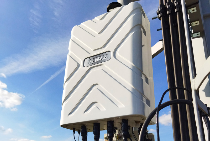
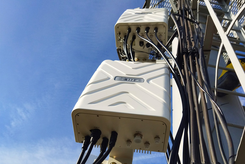
oDAS RADIUS is intended to provide cellular coverage along railways, roads and rural areas. The system allows increasing network capacity efficiency.
The system is designed for integration with LTE FDD, UMTS, GSM (GSM-R) networks, and provides serial distribution of a base station (BTS) sectors (frequency bands) at the distance of 60 km reducing infrastructure cost (CAPEX/OPEX).

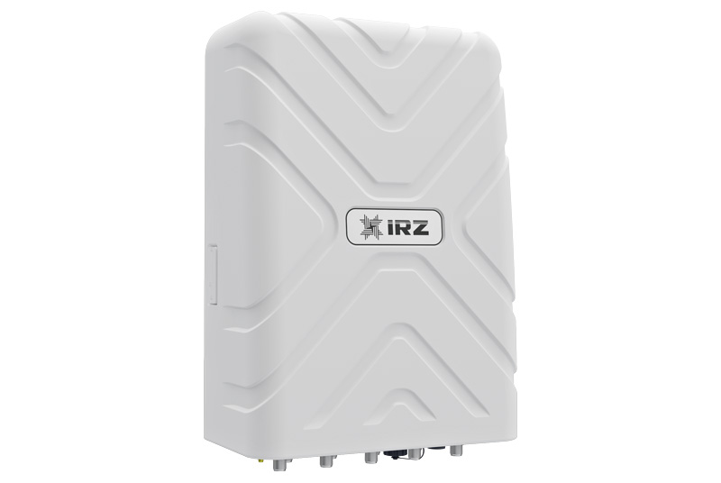
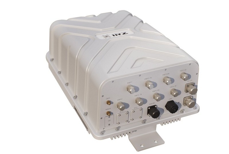
The RADIUS FSC unit is installed at the site with a base station and receives the GSM, LTE, UMTS carriers from it. Then the unit converts them and transmits via MWL or fiber optic over a distance.
The oDAS RADIUS FSR unit is installed at the remote site. It receives the carriers using MWL or fiber optic and provides creation of several sectors similar to that of the BTS. In addition, it amplifies and transmits the received signals further along the line to the next site equipped with oDAS RADIUS products.
| Parameter | Value |
|---|---|
| Type of the units’ connection | — microwave link (MWL) — fiber optic (FO) |
| Number of the retransmission hops (MWL) | GSM/UMTS — up to 3, LTE — up to 2 |
| Number of the retransmission participants (fiber optic) | 4 and more (depending on the distance between FSC unit and the last FSR unit in the line and from the number of repeated retransmission in the retransmission line of the one carrier frequency nominal (GSM / LTE / UMTS) |
| Parasitic noise level intro¬duced by the system into the communication line | ≤ 3 dB (for maximum number of hops and different nominals of GSM / LTE / UMTS carrier frequencies transmitted in each hop) |
| Compliance with international standards | ETSI TS 125 106, ETSI TS 136 106, ETSI TS 145 005, ITU-R F.384-11 (03/2012) |
| Management and control | — locally (Ethernet) — remotely (via the built-in GSM / UMTS / LTE modem) |
| Retransmission channel (MWL) | |
| Frequency band | 6590—7100 MHz |
| Total frequency band width | up to 50 MHz |
| Transmitter output power in the retransmission channel of the FSC / FSR unit | up to 23 dBm |
| Integrated wireless router in the retransmission channel (MWL) | |
| Type of the wireless connection | point-to-point or serial relay connection |
| The frequency band allocated for a high-speed data transmission line in the retransmission channel | 5 / 10 / 15 / 20 MHz |
| Bitrate in the line | up to 50 Mbit |
| Type of modulation | up to 64 QAM |
| Parameter | Value |
|---|---|
| Possible combinations of signals (fiber optic) | |
| Retransmitted signals from FSС / FSR (fiber optic) | — up to 3 pairs of signals with a total frequency band of each pair of not more than 50 MHz — each pair of signals supports its frequency range — each pair of signals supports up to 4 LTE / UMTS carriers and up to 8 GSM carriers |
| MIMO support (fiber optic) | up to 3 pairs of MIMO 2x2 signals |
| Possible combinations of signals (MWL) | |
| Retransmitted signals from BTS to FSR (MWL) | — up to 2 pairs of signals of the total bandwidth of all signals of up to 50 MHz — each pair of signals supports up to 4 LTE / UMTS carriers and up to 8 GSM carriers |
| MIMO support (MWL) | up to 2 pairs of MIMO 2x2 signals |
| Number of the inputs/outputs from the BTS (fiber optic) | up to 6 |
| Number of the inputs/outputs from the BTS (MWL) | up to 4 |
| Number of the optic connectors in the FSC unit | 2 |
| Maximal signal level at the FSC input | up to 48 dBm |
| Type of connectors to connect optic transceivers | SFP+ |
| Number of the integrated transceivers of the module and the antenna’s inputs of the retransmission channel | up to 2 |
| Delay per unit | 7 ms |
| Type of the unit synchronization | GPS / GLONASS by the LTE channel signal |
| Housing protection rating | IP65 |
| Overall dimensions | 610x380x270 mm |
| Weight | up to 20 kg |
| Power consumption | up to 35 W (fiber optic) up to 95 W (MWL) |
| Supply voltage | –48 V |
| Working temperature range | –40…+55 °C –60…+55 °C (optional) |
| Parameter | Value |
|---|---|
| Possible combinations of signals (fiber optic) | |
| Retransmitted signals from BTS to FSR (fiber optic) | — up to 3 pairs of signals with a total frequency bandwidth of each pair of not more than 50 MHz (each pair of signals supports its own frequency range) — each pair of signals supports up to 4 LTE / UMTS carriers and up to 8 GSM carriers |
| MIMO support (fiber optic) | up to 3 pairs of MIMO 2x2 signals |
| Possible combinations of signals (MWL) | |
| Retransmitted signals from FSC / FSR (MWL) | — up to 2 pairs of signals with a total frequency bandwidth of all signals of up to 50 MHz — each pair of signals supports up to 4 LTE / UMTS carriers and up to 8 GSM carriers |
| MIMO support (MWL) | up to 2 pairs of MIMO 2х2 signals |
| Number of the GSM / UMTS / LTE transceivers supported by the FSR unit (fiber optic) | up to 6 — for SM module it is possible to connect external transceivers |
| Number of the GSM / UMTS / LTE transceivers supported by the FSR unit (MWL) | up to 4 — for SM module it is possible to connect external transceivers |
| Number of the pluggable external GSM / UMTS / LTE transceivers (SM module) | up to 2 |
| Number of the carrier frequencies for the one GSM / UMTS / LTE transceiver of the FSR unit | up to 2 |
| Maximal output power of the GSM / UMTS / LTE transmitter | from 40 to 43 dBm depending on the type of the connected transceiver |
| Type of the connector to connect optic transceivers | SFP+ |
| Number of the integrated transceivers of the module and the antenna’s inputs of the retransmission channel | up to 2 |
| Type of the unit synchronization | GPS / GLONASS by the LTE channel signal |
| Delay per unit | 19 ms |
| Housing protection rating | IP65 |
| Overall dimensions | 610x380x270 mm |
| Weight | up to 22 |
| Power consumption, a unit without a transmitter | up to 100 W (fiber optic) up to 200 W (MWL) |
| Supply voltage | –48 / 220 V |
| Working temperature range | –40…+55 °C –60…+55 °C (optional) |
| Parameter | Vale | |
|---|---|---|
| Transceivers of 1800 MHz band | ||
| Operating frequency range | 1710—1785 — UL, 1805—1880 — DL MHz | |
| Power consumption | 40 dBm | |
| Power consumption | 45 W | |
| Overall dimensions for the outdoor SM module | 73х152х285 | |
| Number of НF connectors for connecting the SM module to the FSR unit | 3 (RX, TX, FB) | |
| SM module power supply | via НF-link | |
| Transceivers of 900 MHz band | ||
| Operating frequency range | 873—915 — UL, 918—960 — DL MHz | |
| Transmitter output power | 43 dBm | |
| Power consumption | 110 W | |
| Overall dimensions for the external SM module | 610х380х270 mm (SM module with two integrated transceivers) | |
| Number of HF connectors for connecting the SM module to the FSR unit | 3 (RX, TX, FB) | |
| SM module power supply | via HF-link | |
| Transceivers of 2100 MHz band | ||
| Operating frequency range | 1920—1980 — UL, 2110—2170 — DL MHz | |
| Output power of the transmitter | 40 dBm | |
| Power consumption | 45 W | |
| SM module overall dimensions | 73х152х285 mm | |
| Number of HF connectors for connecting the SM module to the FSR unit | 3 (RX, TX, FB) | |
| SM module power supply | via HF-link | |